 dsale@topsfp.com
 English
 русский
 español
 العربية
 中文
中文



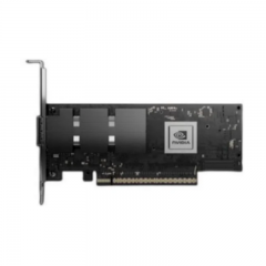
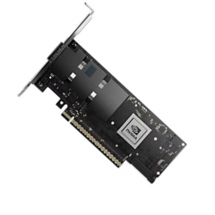
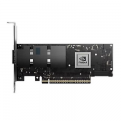
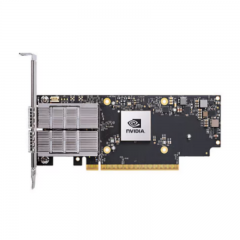
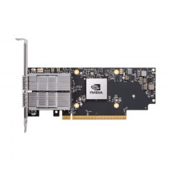
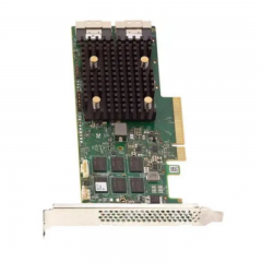
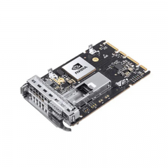
A 10G-to-25G upgrade is a link and capacity migration
Moving server-facing or aggregation links from 10GbE to 25GbE is a network-capacity project, not a “network transformer” product change. The upgrade affects endpoint ports, NICs, switches, software images, optics or cables, fiber channels, FEC settings, port profiles, traffic patterns, redundancy, and operating procedures. A successful migration begins with the workload and the existing physical infrastructure rather than a generic claim about high-rate equipment.
IEEE’s 25 Gb/s Ethernet task force completed its work with the approval of IEEE Std 802.3by-2016. That standard provides a foundation for 25GbE interfaces, but a production deployment must still use the current compatibility and configuration documentation for the exact NIC, switch, optical module, cable, and software release. A 25G label alone does not prove interoperability.
Establish the capacity and traffic objective
Document why the upgrade is required. Identify the server, storage, application, and east-west traffic patterns that are constrained by the current 10G links; record peak and sustained utilization, congestion points, latency sensitivity, redundancy design, and expected growth. Then determine whether 25GbE is the appropriate per-port step, whether uplinks also need change, and how the leaf, aggregation, or spine capacity will be affected.
Do not evaluate access-port speed in isolation. A 25G server connection can change uplink demand, buffering behavior, oversubscription policy, and power or cooling requirements. The correct ratio between server-facing and uplink capacity is workload-specific. Build a capacity model for normal operations, maintenance, and failure scenarios instead of adopting one universal oversubscription number.
Create a migration inventory. For each link, record the two endpoint devices and ports, hardware revision, driver or network-operating-system version, current rate, supported rates, existing media, fiber type, route length, connector system, port profile, FEC state, and acceptance result. This prevents physical and software constraints from being discovered only during a production change window.
Validate both host ports and software
Check the vendor’s compatibility matrix and release notes for the exact NIC and switch ports. Confirm that the selected port group supports 25GbE, the required optical or cable family, any breakout arrangement, and the target software version. An SFP28-shaped port is necessary for common 25G pluggables, but it is not a universal promise of support for every module, cable, or configuration.
Cisco’s 25G SFP28 data sheet illustrates a portfolio with DAC, AOC, short-reach multimode, and longer-reach single-mode options. It also shows that host configuration can vary across media and applications. Treat such documentation as an example of the product-specific checks required; the actual host vendor’s matrix and the chosen part number remain the decision authority.
Confirm the operating mode at both ends before the change. Check speed, port breakout configuration where relevant, FEC requirements, autonegotiation behavior where supported, and any platform-specific commands. A link may be physically detected but remain down or report errors when the endpoints do not agree on rate, FEC, or the selected interface profile.
Select the physical medium by route
Choose the physical layer from the actual channel and operations model. Very short in-rack or adjacent-rack runs may use direct-attach copper when the endpoints, length, and FEC requirements fit. Active optical cables can simplify short fiber runs with fixed endpoints and length. Separate SFP28 optics with multimode or single-mode patching can be more adaptable for structured cabling, distribution frames, or routes expected to change.
Measure the real route through trays and managers, not just the straight-line distance between devices. Include equipment cords, patch panels, cross-connects, trunks, adapters, and service slack. Verify the fiber category, connector type, number of mated connections, polarity, and channel loss against the selected module’s current data sheet. Do not inherit a 10G reach or patching assumption for a 25G application without validating the new module and link budget.
For a cable assembly, record the exact part number and length. For separate optics, record the module pair, wavelength, fiber type, connector interface, and any complementary requirement. Avoid a procurement description that says only “25G SFP28”; it does not contain enough information to build a reproducible link.
FEC, diagnostics, and acceptance
Forward Error Correction must be considered early in a 25G project. Cisco’s 25G SFP28 data sheet documents FEC requirements for parts of its portfolio, including AOC links. The needed setting depends on the actual host and medium. Do not copy a FEC setting from a 10G port, a different switch family, or a different cable length. Confirm the selected configuration against both endpoint vendors’ current guidance.
Where available, use module diagnostics and interface counters to establish a baseline. Check identity, reported cable or module details, temperature, optical power, alarms, and error counters as supported by the host. Interpret diagnostics using the exact module data sheet. A normal-looking diagnostic field does not by itself prove correct FEC, fiber type, port profile, or traffic performance.
Acceptance should include more than link-up. Verify operational rate, counter stability, alarms, and sustained traffic behavior. Test redundant paths and relevant application flows. Record the final port configuration, module or cable identifiers, endpoint software versions, route, test result, and any exceptions so that the link can be supported and replaced consistently.
Plan a staged migration
- Classify links by workload, dependency, physical medium, hardware support, and change risk.
- Qualify the exact NIC, switch, module or cable, FEC profile, and software image on a representative nonproduction or pilot link.
- Prepare approved port configurations, cable labels, rollback procedures, and monitoring baselines.
- Migrate a controlled group of links, verify rate, traffic, counters, and redundancy, then update the records.
- Review capacity and operational observations before extending the rollout to the next group.
A staged approach is safer than replacing every 10G link at once. It also produces practical evidence about compatibility and configuration that can be reused for similar ports and routes.
Technical request checklist
A request for a 10G-to-25G upgrade should identify the two host platforms and ports, target application, operating rate, software versions, proposed media and exact route, fiber type and connector system, FEC and port-profile requirements, environmental constraints, compatibility or coding needs, quantity, labeling, and acceptance test. Request current data sheets for the proposed optics or cables and compatibility confirmation for the named hosts.
The goal is a verified 25GbE service with a clear capacity purpose, not a generic high-speed component substitution. When the host, medium, FEC, channel, configuration, and tests agree, the migration improves capacity while preserving operational control.
