 dsale@topsfp.com
 English
 русский
 español
 العربية
 中文
中文



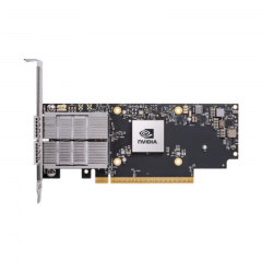
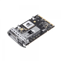
There Is No Universal Winner Between 200G and 400G
200G and 400G Ethernet serve different roles in data center networks. The right choice depends on the workload, topology, installed base, traffic profile, available fibre, port density, power and cooling envelope, host-platform support, budget, and migration plan. A higher aggregate rate is not automatically the best solution if it creates unused capacity, unsupported breakouts, difficult cabling, or an operating model the team cannot maintain.
Start with the service requirement. Is the link connecting servers to a leaf switch, leaf switches to a spine layer, storage systems to a fabric, a data hall to aggregation, or two sites over a transport network? Define the required throughput, latency sensitivity, redundancy, expected growth, and the consequences of a failure. This context helps determine whether 200G, 400G, or a different interface is appropriate for that part of the architecture.
Ethernet standards development covers multiple rates and physical-layer options. The specific product configuration must still be checked against the current host-platform compatibility matrix and product data sheet. A speed label does not define the number of electrical lanes, optical lanes, fibre count, reach, connector, FEC setting, form factor, or supported breakout behavior.
Model the Traffic Before Selecting Ports
Build a traffic model from measured data and planned workloads. Identify north-south traffic to users or external services, east-west traffic between applications, storage and backup flows, AI or analytics data movement, management, replication, and security inspection. Record typical and peak utilisation, growth assumptions, burst behavior, and the services that must be protected during a failure.
Use the model to define capacity at each layer. A server-facing link may have different requirements from a spine uplink or data-center interconnect. The appropriate oversubscription ratio, redundancy method, and capacity headroom depend on the service objective. Do not use a generic one-to-four or one-to-two pattern without confirming that it fits the host interfaces, actual traffic, and failure scenario.
Plan for both normal operation and degraded operation. If a link, device, or path fails, identify which remaining links will carry the traffic and whether priority services still receive the required capacity. This may influence the choice between 200G and 400G more than the average utilisation alone.
Understand Lanes, Form Factors, and Breakouts
Aggregate speed can be delivered through different lane structures and module form factors. The host platform defines which combinations are supported. A 200G or 400G port may support a particular set of optics, cables, and breakout configurations, but these capabilities vary by switch, router, network adapter, software release, and hardware revision.
Breakout should be treated as a planned design feature, not an adapter purchased at the last moment. Confirm the host port mode, supported breakout type, downstream interface rate, cable or fibre assembly, lane mapping, configuration commands, monitoring behavior, and operating-system support. A breakout that is physically connected but not supported by the platform will not provide a usable service.
Record the form factor and thermal assumptions. Different platforms have different port density, cooling, power, and mechanical constraints. The right module must fit the port and be supported at the required operating temperature and traffic profile. Refer to the host vendor’s current documentation before approving a form factor or a high-density deployment.
Select the Physical Layer for the Actual Path
The physical medium is an engineering decision. For each link, document the endpoints, required rate, fibre or cable type, connector, route length, patch panels, splices, environment, redundancy, and future expansion. Decide whether the path requires multimode fibre, single-mode fibre, direct-attach copper, active electrical cable, parallel fibre, or a wavelength-multiplexed solution based on the approved application and vendor support.
Do not compare optical products only by speed. Two 400G modules can have different reaches, connector types, fibre requirements, lane structures, optical budgets, power characteristics, and compatibility constraints. The same is true at 200G. Read the exact physical-layer specification and data sheet, then validate it against the installed cabling plant and the host platform.
Calculate or verify the actual link budget when optical fibre is used. Account for fibre attenuation, connector and splice loss, patching, route length, and the operating limits specified for the chosen interface. If a link uses several passive components, long fibre routes, or transport equipment, include these in the design review. A nominal product reach is not a complete acceptance test.
Confirm FEC, Software, and Interoperability
Forward error correction is a critical configuration item for many higher-rate Ethernet links. The expected FEC behavior depends on the Ethernet physical layer and the host implementation. Confirm the supported setting at both ends of the link, document any required configuration, and verify it during staging. A mismatch can prevent the link from establishing or create error conditions that are difficult to interpret.
Software and firmware matter as much as optics. Record the switch, router, or adapter model; hardware revision; operating-system or network-software version; module support matrix; and relevant release notes. An interface that is supported on one software version may require a different configuration or have different limitations after an upgrade.
For multi-vendor links, validate the exact combination. Agree on the physical layer, FEC behavior, optical media, monitoring expectations, test method, and escalation boundary. Do not infer interoperability from a shared speed or form factor. Use a controlled test environment when the link supports important customer, storage, management, or production traffic.
Plan the Migration Path
A migration should be based on the current network and the next verified demand stage. Inventory the existing server interfaces, switch ports, fibre plant, patch panels, optics, power, cooling, management tools, and maintenance practices. Identify which components can remain in service and which must change to support a new link rate or topology.
Use staged deployment. Start with a representative set of links, validate throughput, error behavior, monitoring, failover, and operational procedures, then expand after the expected checks pass. This approach reveals issues in cabling, FEC, software, or host support before a wide production rollout.
Keep alternatives documented. A 400G-ready platform may be valuable for an eventual upgrade, but that does not mean every current link should be deployed at 400G. Conversely, a 200G deployment may be an appropriate step when it matches available server interfaces, capacity demand, and the intended lifecycle. The decision should be revisited as real traffic, hardware support, and service requirements change.
Commission and Monitor the Service
Acceptance testing should verify more than interface status. Confirm that the correct cable or module is installed, the configured rate and FEC behavior are expected, the physical path matches the record, error counters are acceptable, and traffic passes between the real endpoints. Test application-relevant throughput, packet loss, latency where relevant, redundancy, monitoring, and alerting.
Collect evidence for handover. Record the host and software version, interface configuration, physical-layer choice, fibre or cable information, test results, monitoring baseline, asset identifiers where required, and replacement option. These records shorten troubleshooting and make a later move, upgrade, or replacement safer.
Monitor the link after deployment. Watch utilisation, errors, flaps, diagnostics where supported, temperature, and capacity. Review the data after application releases, traffic growth, software upgrades, or changes to the fibre path. The objective is to identify margin loss before it becomes a customer incident.
Procurement Questions That Matter
Before issuing an RFQ, define the required host platform, interface speed, physical-layer standard, form factor, FEC behavior, fibre or cable type, connector, reach, breakout requirement, software version, quantity, temperature environment, test scope, and delivery schedule. Ask the supplier to identify assumptions and provide compatibility evidence for the intended platform.
Compare options against the approved technical design, not only unit price. Include included accessories, compatibility, staging, warranty or support process, availability basis, replacement strategy, power and cooling, and the cost of a delayed deployment. A lower-priced option that requires rework or does not support the host configuration may increase the total project cost.
Practical Decision Framework
Choose 200G or 400G only after confirming the application, traffic model, fault tolerance, host support, physical path, FEC, software, form factor, monitoring, and migration plan. Use the rate that meets the current service requirement while preserving a credible, tested route to the next stage. This evidence-based approach is more reliable than declaring one Ethernet rate the winner for every data center.
Further Reading
For standards-development context, review the IEEE 802.3 Ethernet Working Group, the IEEE P802.3cd baseline archive for 50G, 100G, and 200G Ethernet, and the IEEE Beyond 400 Gb/s study-group archive. Use current platform and product documentation for any specific deployment approval.
