 dsale@topsfp.com
 English
 русский
 español
 العربية
 中文
中文



Expansion Starts with Service Requirements
A data center expansion is not only a construction project or a hardware purchase. It is a service decision that affects availability, customer commitments, security, operating cost, and the ability to respond to future demand. Before choosing a building, rack layout, or network platform, define what the expanded environment must deliver. Document the workloads to be supported, expected growth range, latency sensitivity, geographic requirements, recovery objectives, maintenance expectations, and the teams that will own daily operations.
Separate confirmed demand from forecasts. A forecast can guide capacity planning, but it should not be treated as a guaranteed order. Use a phased plan that can add capacity at deliberate checkpoints. This approach helps teams avoid building too far ahead of demand while preserving sufficient power, cooling, floor, and network options for the next phase. Every phase should have a clear trigger: committed customer demand, measured utilisation, resilience requirements, or a planned retirement of older equipment.
Select a Site with Resilience and Operations in Mind
Location affects much more than travel time. Review utility access, power availability, fibre routes, carrier diversity, local permitting, natural and environmental risks, loading access, security, and the availability of qualified operations support. If a facility will serve critical applications, avoid relying on a single building entrance, single carrier path, or single upstream dependency. Ask providers to explain physical route diversity rather than assuming that two contracts automatically mean two independent paths.
Network proximity matters as well. Identify where customers, cloud on-ramps, internet exchanges, and partner networks connect, then estimate the practical path to each. A low map distance does not guarantee a low-latency or resilient route. Validate the handoff location, cross-connect process, demarcation point, repair responsibilities, and test procedure. Keep copies of circuit records, escalation contacts, and service-level documents with the operational runbook.
For multi-site design, decide what role each site will play. One location may be the primary production site, another may provide disaster recovery, and a third may offer regional capacity or development resources. The architecture must match the role. A recovery site needs tested data protection, application dependencies, access controls, and operating procedures; simply having spare racks in another city is not a recovery strategy.
Plan Power and Cooling as a System
Capacity planning should use measured load data wherever possible. Inventory existing equipment, its typical and peak power draw, redundancy requirement, and expected lifecycle. Include not only compute and storage, but also network devices, optical transport, management systems, lighting, security, and the power used by supporting infrastructure. Create an engineering estimate with stated assumptions, then update it as deployment designs become more detailed.
Consider the full power path: utility feed, transformers, switchgear, UPS systems, generators where applicable, distribution units, rack-level delivery, and monitoring. Identify single points of failure and the maintenance operations that could reduce redundancy. A design may have multiple components on paper but still share a common upstream room, cable tray, control system, or maintenance dependency. Document those shared elements honestly so that risk decisions are visible.
Cooling design must track the intended rack density and airflow pattern. High-density equipment can change the needs of a room much faster than average-rack assumptions suggest. Work with qualified facility engineers to evaluate containment, air distribution, temperature and humidity monitoring, water or refrigerant risks, maintenance access, and the operating limits specified by each equipment vendor. Measure conditions at the rack and equipment intake, not only at a room-level sensor.
Design a Network That Can Grow Predictably
The expansion network should be based on traffic patterns, failure domains, and operational simplicity. Map east-west application traffic, north-south customer or internet traffic, backup and replication flows, management access, and expected storage or AI workload demands. Assign capacity and resilience requirements to each type of traffic. This prevents a single large uplink from becoming an unexpected bottleneck when a new service is introduced.
Use a consistent physical and logical architecture where it fits the environment. Standardised leaf-spine or routed designs can make capacity and fault domains easier to understand, but the appropriate design depends on existing equipment, skills, and service requirements. Confirm interface types, supported speeds, reach limits, fibre type, connector type, breakout requirements, software compatibility, and power budgets before procurement. An optical module that fits physically is not necessarily supported by the host platform or correct for the intended link.
Document every link from panel to port. Include the route, fibre count, polarity, connector format, length, installed optics, intended speed, test results, and ownership. Maintain clean separation between production, management, storage, and out-of-band paths where the security model requires it. For critical links, test the actual failover behavior during a planned window. Redundancy should be proven by traffic and monitoring results, not inferred from two visible cables.
Procurement and Compatibility Discipline
Expansion projects often involve equipment from different generations. Create a bill of materials that records manufacturer part numbers, firmware or software prerequisites, supported transceiver matrix, power needs, lead-time risk, and approved substitutes. Ask suppliers for a written compatibility statement when an item is intended for an existing platform. Validate any substitute in a controlled environment before it enters a production path. Keep the test notes with the asset record so future operators understand what was verified.
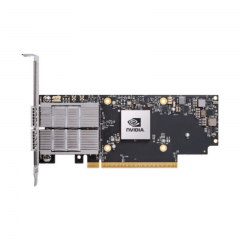
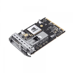
Do not order based only on a speed label. A 100G, 400G, or 800G interface can support multiple optical reaches, modulation methods, connector styles, and breakouts. The correct selection depends on the switch or router port, the installed fibre plant, link length, topology, environmental requirements, and the platform vendor’s support policy. The same discipline applies to servers, GPUs, network adapters, storage, and power components: part-number compatibility, firmware alignment, and thermal design should be checked before deployment.
Build a receiving and staging process. Verify quantities, model numbers, serial numbers where required, packaging condition, and accessories against the approved order. Record the items in inventory, test representative units, apply approved firmware or configurations, and label the equipment before it enters production. A small amount of staging time reduces the risk that a wrong item is discovered during a customer-impacting window.
Security, Monitoring, and Day-Two Readiness
Security should be built into the expanded environment from the first design review. Define management-network isolation, access roles, authentication methods, logging, physical access controls, vulnerability management, and the handling of temporary installation access. Remove default credentials, protect configuration backups, and ensure that telemetry does not expose sensitive information. Review supplier and contractor access so that it is time-bound, necessary, and auditable.
Monitoring must be ready before service onboarding. Establish baseline telemetry for power, cooling, environmental conditions, device health, interfaces, packet errors, latency, capacity, and application service checks. Route alerts to owners who can act, and connect those alerts to current asset and circuit records. During the first weeks of operation, review trends frequently. This is the period when an incorrect capacity assumption, a marginal optical link, or a missing dependency is most likely to appear.
Prepare the operational materials that turn a design into a dependable service: rack diagrams, network diagrams, port maps, escalation contacts, maintenance procedures, spare-part strategy, incident communication templates, and recovery runbooks. Run at least one tabletop exercise and, where safe, a controlled failover test. Record what worked, what took longer than expected, and which documentation was missing.
Use a Phased Acceptance Process
Before each phase goes live, use an acceptance checklist that covers facilities, hardware, network, security, monitoring, documentation, and support. Confirm that work orders are closed, test evidence is available, inventory is accurate, and accountable owners accept the environment. Validate the customer-facing path, not just individual components. A server that powers on, a switch that has link, and a circuit that has carrier light can still fail to deliver the intended service together.
After acceptance, compare the actual deployment against the planning assumptions. Track utilisation, incident patterns, energy use, change success, and time required to provision the next customer or workload. These outcomes should inform the next expansion phase. Good expansion planning is iterative: it balances demand, technical constraints, and operational evidence instead of treating capacity as a one-time construction target.
Conclusion
A successful data center expansion joins facilities engineering, network design, procurement, security, and service operations around the same objective: reliable capacity that can be operated and changed safely. Start with explicit requirements, test assumptions in stages, verify compatibility and physical paths, and require evidence before declaring a phase ready. That approach gives teams a practical foundation for growth without overstating capabilities or relying on untested redundancy.
