 dsale@topsfp.com
 English
 русский
 español
 العربية
 中文
中文



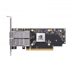
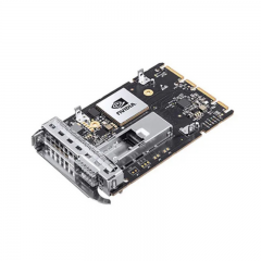
DWDM networks are designed around controlled spectrum and optical paths
A dense wavelength-division multiplexing (DWDM) network carries multiple optical channels over shared fiber infrastructure. Its value comes from using spectrum in a planned, repeatable way—not from placing several colored transceivers on the same fiber without system engineering. Every service requires a defined channel, compatible endpoint optics, a passive or active optical path, a calculated budget, and an operations process that prevents conflicts during expansion.
DWDM design begins with the service and transport architecture. Identify the required client rates and protocols, endpoints, route lengths, availability objectives, expected growth, existing fiber infrastructure, and the type of optical transport system to be used. A simple passive point-to-point path and an amplified multi-span network have different requirements and must not be engineered as if they were the same environment.
Establish the grid and the channel plan
ITU-T Recommendation G.694.1 defines spectral grids for DWDM applications. Use the applicable grid as the basis for a controlled channel plan. For every circuit, record the channel identifier, center frequency or wavelength, transceiver or transponder, mux/demux port, fiber route, service, working or protection role, and owner. Keep this record synchronized with the actual rack labels and equipment configuration.
Channel allocation must consider current services and planned expansion. Reserve capacity deliberately for protection, growth, test, or maintenance according to the design. Do not assign a channel independently at one site; the far-end module, passive path, and transport equipment must be configured to the same plan. A channel conflict can affect services that are physically separate at the equipment-port level but share the same fiber spectrum.
Do not copy a channel count from a product brochure into a network design. The usable spectrum, spacing, filter bandwidth, supported baud rate, optical reach, and equipment capabilities are system-specific. The exact platform, passive components, and transceiver documentation determine the valid design envelope.
Choose the appropriate optical architecture
A DWDM network can use passive mux/demux panels, optical add/drop modules, transponders, amplifiers, dispersion management where applicable, optical monitoring, and ROADMs or other reconfigurable systems. The architecture should be selected by topology and operations need. A static point-to-point link may be served by passive components and a controlled fixed channel plan. A ring, multi-site, or frequently changing network may need add/drop or reconfigurable capabilities and more formal transport controls.
Passive components combine or separate wavelengths but add insertion loss. Cisco’s NCS 1000 mux/demux patch-panel documentation illustrates that passive mux/demux equipment is an integrated optical component with defined channel and filter characteristics. Do not treat it as a transparent patch panel. Include every passive port, patch cord, monitor, filter, and connector in the optical budget and maintenance record.
Transponders and pluggable optics also differ in their host-side and optical-side behavior. Cisco’s 10GBASE DWDM SFP+ documentation, for example, distinguishes fixed-wavelength and tunable modules and notes different electrical receiver requirements for specific tunable families. This is a reminder to validate the host interface and software as carefully as the optical channel.
Calculate reach and optical margin end to end
For each circuit, calculate the end-to-end optical budget. Start with the exact transmitter output and receiver sensitivity/overload limits from the proposed data sheet. Add fiber attenuation, splices, connectors, patch panels, mux/demux insertion loss, OADM pass or add/drop loss, monitoring loss, filters, amplifiers, and a defined engineering margin. Perform the calculation for the actual port-to-port path, not merely the route distance.
Check high-power as well as low-power conditions. A short link or amplified path can overload a receiver even when the received signal appears strong. An attenuator may be required only when the exact module and design calculations show it; generic distance rules are not sufficient. Cisco’s DWDM SFP+ documentation explicitly notes the potential need for attenuation on shorter single-mode fiber paths for certain specified modules.
Long, amplified, high-density, or multi-span DWDM systems require additional design checks. Chromatic dispersion, OSNR, nonlinear effects, amplifier gain and tilt, channel loading, and FEC or coherent-detection behavior can affect service quality. These cases require an optical-transport engineering design and should not be accepted based on a simple link-up indication.
Compatibility, client interfaces, and management
The client or host port and the DWDM optical interface are separate validation points. Record the source equipment, port type, hardware revision, software release, supported application rate, module coding, power limit, FEC mode, and any required EDC, DSP, or application selection. Confirm the peer equipment provides the corresponding service and optical behavior.
For third-party or compatible optics, qualify the precise module, host combination, and software release before volume deployment. A physical SFP+ or QSFP fit is not proof of interoperability. Document port settings, actual diagnostic visibility, rate, FEC, alarms, and error-counter behavior during the qualification test.
Use digital optical monitoring, optical spectrum measurements, and transport alarms where available. Establish a baseline for transmit and receive power, temperature, voltage, bias, pre-FEC/post-FEC indicators when applicable, and error counters. Compare measurements with the designed budget and exact product limits. Do not use one module family’s thresholds as a generic threshold for a different optical technology.
Design protection and operations together
Availability requires more than dual optics. Define working and protection paths, identify shared fiber routes, passive components, racks, power feeds, and equipment dependencies, and document the intended switchover process. Two circuits that share a mux/demux, pathway, or fiber cable may not provide the diversity the service requires.
Adopt a formal change process for wavelengths and optical paths. Before adding, moving, or retuning a channel, check the channel plan, protection impact, mux/demux or ROADM port mapping, budget, endpoint ownership, and expected alarms. After the change, run the acceptance checks and update the circuit record immediately. Undocumented wavelength changes are a major operational risk in shared-spectrum networks.
Commissioning procedure
- Confirm the service endpoints, client interfaces, software versions, compatible optics or transponders, and protection design.
- Verify the approved G.694.1 grid, channel allocation, mux/demux or add/drop ports, fiber route, and optical budget.
- Inspect and clean optical connections; label all common, line, channel, monitor, and client ports.
- Configure the approved channel, host interface, and FEC or application settings at both endpoints.
- Validate link state, optical levels, diagnostics, alarms, error counters, and any applicable spectrum or transport measurements.
- Run sustained service and protection tests, then record the final channel plan, configuration, measurements, and acceptance result.
Technical request checklist
A DWDM network request should identify the required services and rates, endpoints and port types, topology, grid and channel plan, fixed or tunable requirements, fiber routes, mux/demux, OADM, ROADM, and amplification details, loss and dispersion inputs, protection objectives, connector types, environment, host compatibility needs, monitoring requirements, quantity, labeling, and acceptance criteria. Request the current data sheets for all active and passive components.
The correct DWDM outcome is a documented optical network in which spectrum, hosts, passive components, optical margin, protection, and operations controls agree. That discipline makes capacity expansion possible without turning shared fiber into an unmanaged risk.
