 dsale@topsfp.com
 English
 русский
 español
 العربية
 中文



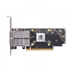
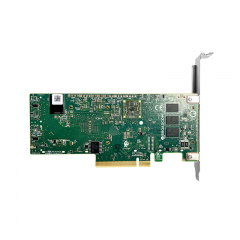
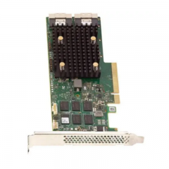
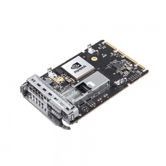
A practical guide to form factors, lane architecture, breakout, cooling and end-to-end qualification for network engineers and B2B buyers.
Technical review: November 11, 2026

Figure 1. AI-generated editorial illustration of optical networking hardware. The module shapes are conceptual and do not identify specific products or prove compatibility.
In an AI cluster, a transceiver purchase can go wrong even when the order contains the correct headline speed. A module may use the wrong cage, expect a different electrical interface, require an unsupported breakout mode, or exceed the host’s thermal qualification. The result is a link that cannot be deployed as intended.
OSFP and QSFP-DD are form-factor families, not performance rankings. Both have implementations for 400G and 800G networking. The right choice starts with the switch or adapter, then follows the complete link: host interface, optics, fiber, remote endpoint, configuration and cooling.
Why this decision matters for AI infrastructure
Distributed training and some distributed inference deployments exchange substantial traffic between servers. Their network requirements depend on workload placement, communication patterns, topology and congestion. A faster optic alone cannot resolve an oversubscribed fabric or an endpoint bottleneck.
Industry development is nevertheless pushing toward greater bandwidth density and better energy efficiency. In October 2026, NVIDIA and Cisco announced plans for USFP, a future pluggable ecosystem using 400Gb/s-per-lane electrical signaling. This is a roadmap signal, not a reason to assume today’s OSFP and QSFP-DD ports can accept a new form factor. For an existing project, qualify what the installed hardware actually supports. [NVIDIA/Cisco announcement]
OSFP vs QSFP-DD: the essential comparison
OSFP means Octal Small Form Factor Pluggable. The OSFP MSA describes eight high-speed electrical lanes and variants with an integrated heatsink or a host-provided riding heatsink. QSFP-DD means Quad Small Form Factor Pluggable Double Density; its double-density interface extends the QSFP family to eight lanes. Generation-specific hardware specifications matter more than the family name. [OSFP MSA] [QSFP-DD hardware specification]
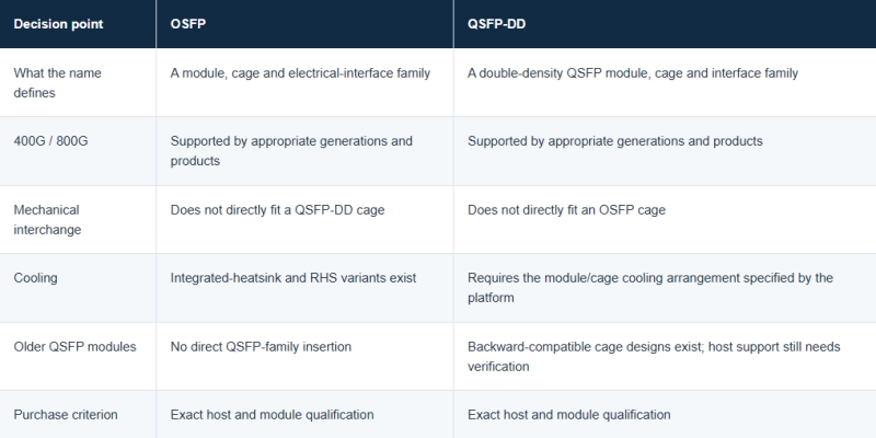
QSFP-DD’s backward-compatibility advantage is directional. A supported QSFP-DD port may accept selected older QSFP modules; an older QSFP cage does not thereby become a QSFP-DD port. Nor does mechanical insertion establish the required speed, software support or optical interoperability. Cisco explicitly directs buyers to its platform compatibility matrix. [Cisco QSFP-DD800 data sheet]
Separate electrical lanes from optical lanes
A lane is an individual signaling path. On the host side it is electrical; across the fiber it is optical. A transceiver can map one lane arrangement to another, so the counts need not match.
At a simplified nominal-rate level, 400G may use eight 50G host lanes or four 100G host lanes. A common 800G host arrangement uses eight 100G lanes. These shorthand figures describe aggregate capacity; they are not the exact encoded line rates. The supported application must match the host’s lane arrangement and signaling generation. [QSFP-DD specification]
A useful example is NVIDIA’s documented 400G QSFP-DD DR4 implementation: eight 50G-PAM4 electrical lanes map to four 100G-PAM4 optical lanes. It illustrates why different host interfaces can still connect across a matched optical link. Conversely, two modules with “400G” on their labels are not automatically interoperable. [NVIDIA LinkX guide]
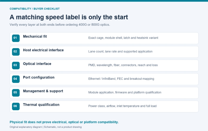
Figure 2. A practical qualification sequence for 400G/800G optics. Check all six layers at both ends of the link.
Can OSFP and QSFP-DD communicate over fiber?
Yes, appropriately specified products can; they do not need identical metal housings. Each module must be supported by its own host, while both optical ends must implement compatible interfaces.
For example, an OSFP module at one end and a QSFP-DD module at the other can form a 400G Ethernet link when their optical specifications, fiber path, port modes and platform qualifications agree. Cisco’s 400G documentation describes interoperability with third-party modules complying with the same applicable standards. That is an interface-level statement, not approval of every vendor combination. [Cisco 400G interoperability guidance]
Check the actual optical PMD—physical medium dependent interface—rather than stopping at speed or connector shape. Match the protocol, wavelength arrangement, optical lane count, reach, transmitter/receiver limits, fiber and connector specification. Confirm FEC and any required host port configuration. A connector that looks right is only one part of this evidence.
Understand “800G” versus “2 × 400G”
Some products advertised with 800G aggregate capacity contain two independent 400G optical engines. Their port behavior differs from a native single 800GbE interface.
NVIDIA’s MMS4X00-NS-T example uses a twin-port OSFP with 800Gb/s of aggregate electrical capacity and two 400G optical interfaces. In a supported configuration, these serve separate 400G endpoints. The purchase must identify the logical port layout, remote optics and fiber assemblies, not simply request an “800G OSFP.” [NVIDIA twin-port documentation]
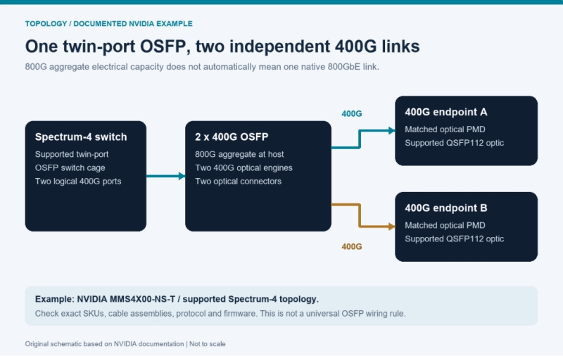
Figure 3. One documented twin-port topology: 800G aggregate host capacity serves two independent 400G links. It is not a universal wiring diagram for all OSFP products.
Breakout is an engineered configuration. An 800G-to-2×400G deployment requires the correct switch mode, module application, lane mapping and remote interfaces. A cable cannot create unsupported logical ports. Similarly, the presence of two connectors does not by itself establish every possible breakout option. Specify the complete topology in the bill of materials.
Finned-top and flat-top OSFP are not interchangeable purchasing descriptions
Thermal design is a functional requirement. An integrated-heatsink OSFP dissipates heat through its module heatsink. OSFP-RHS relies on a riding heatsink supplied by the host. A flat top therefore does not mean that a module operates without cooling. [OSFP MSA thermal variants]
In NVIDIA’s documented Quantum-2/Spectrum-4 and DGX H100/H200 arrangements, switch-side twin-port optics and server-side optics can require different shell and heatsink variants. ConnectX-7 adapters also exist with OSFP or QSFP112 cages, while the documented BlueField-3 configuration uses QSFP112. “For ConnectX-7” is consequently an incomplete ordering description. [NVIDIA endpoint guide]
Ask for the exact adapter SKU, cooling variant, permitted module power and operating conditions. Do not transfer a topology rule from one NVIDIA generation to every OSFP platform.
For budgeting, calculate optics power across the deployment. As an illustrative assumption, 64 populated modules drawing 17 W each represent 1,088 W of module power. This excludes the switch ASIC, fans and other system loads, and is not a measured configuration. It shows why small per-module differences can matter at scale; cooling overhead requires a separate facilities estimate.
Choose fiber and reach from the exact module specification
SR, DR and FR labels describe optical applications, not interchangeable cabling choices. NVIDIA’s definitions include 400GBASE-DR4 over parallel single-mode fiber to 500 m and 400GBASE-FR4 over wavelength-multiplexed single-mode fiber to 2 km. These are interface examples, not universal reach guarantees for everything sold as a 400G module. [NVIDIA optical-interface definitions]
Before reusing a fiber plant, verify its type, route length, connector count, polarity, insertion loss and connector polish. MPO-12 and MPO-16 are distinct interfaces; APC and UPC must not be treated as interchangeable. Inspect and clean connectors using the applicable installation procedures.
Also read product-specific exceptions. The NVIDIA twin-port example above is specified for a particular 100 m application. It should not inherit a 500 m reach merely because another product carries a similar DR label. When a specification gives a channel-loss budget, include patch panels and connectors rather than measuring only the cable length.
Evaluate 400G and 800G at the network level
Start with the workload and topology. For an established 400G cluster, increasing speed may require changes to NICs, switches, software, fiber and power provision. If the workload is constrained elsewhere, new optics may provide little immediate benefit. This is a planning judgment to test with measurements, not a claim that 400G is sufficient for every AI deployment.
Evaluate 800G when endpoint capabilities, uplink demand or port-density requirements justify it. Compare the resulting fabric designs, including oversubscription and failure domains. Higher nominal speed can support a useful redesign, but its value must be demonstrated in the intended configuration.
For short links, include qualified DAC or active-copper options in the comparison. For longer or differently routed links, evaluate optical solutions. Cable reach is specific to the host and cable generation: do not reuse an older-speed distance assumption.
Compare cost per deployable link, including both ends, fiber assemblies, installation, qualification, power, spares and recovery time. A cheaper optic that requires replacing cabling or causes acceptance failures can raise project cost. An alternative requiring more initial expenditure may be justified only if its operational benefit is credible.
A qualification checklist before the purchase order
Use the following as a proposed acceptance workflow. Agree the traffic profile, test duration and pass criteria with the deployment owner before testing.
- Identify both endpoints: exact switch, line card, NIC/DPU SKU, cage type and software/firmware release.
- Define the service: Ethernet or InfiniBand, target speed, native or breakout mode, and logical port mapping.
- Specify both optics: complete part numbers, host applications, optical interfaces and thermal variants.
- Specify the channel: fiber type, connectors, polish, polarity, length and acceptable channel loss.
- Check host qualification: supported optics tables, power limits and any vendor coding or application requirements.
- Record a baseline: module identity, firmware, diagnostics, optical levels and configured FEC.
- Test under representative load: inspect temperatures, alarms, link resets and corrected/uncorrectable FEC behavior against platform criteria. Link-up alone is not the acceptance test.
- Verify recovery: restart and replacement behavior, sample consistency, documentation and spare-part availability.
Management compliance also needs context. OIF’s CMIS provides a common framework for managing modules, including applications and diagnostics. It does not certify a specific optic in a specific switch or guarantee optical interoperability. Retain the platform’s qualification evidence alongside the module specification. [OIF management overview]
Frequently asked questions
Is OSFP faster than QSFP-DD?
No. Compare the specific generation and product. Both families include 400G and 800G implementations. The host platform determines the usable interface and supported mode.
Can I put a QSFP-DD module into an OSFP port?
Not directly. Their mechanical interfaces differ. Any proposed adapter solution must be explicitly supported for the exact platform and speed; do not assume that an adapter creates compatibility.
Does every 800G module support two 400G endpoints?
No. Check whether it is a native 800G interface, a twin-port design, or a product with supported breakout applications. Confirm the host configuration and matching remote optics.
Can an 800G port use an older QSFP module?
Selected QSFP-DD800 platforms support older QSFP-family devices. This is conditional on the host, software and approved module. It is not a general statement about every 800G cage.
Build the link around verified requirements
The useful OSFP-versus-QSFP-DD question is: which complete link is qualified for this deployment? Select the form factor required by each endpoint, match the optical interfaces, verify port modes and cooling, then validate the assembled system.
Topstar’s product scope includes optical transceivers, high-speed interconnects, network adapters and AI-server components. For a configuration-specific quotation, provide the details below so the proposed parts can be checked against the project requirements.
Request a 400G/800G optical-link quotation
Send your endpoint models and SKUs, firmware versions, protocol, required port mode, link distance, fiber/connector specification, cooling variant and quantity. Request complete module and cable part numbers, relevant manufacturer specifications and agreed acceptance criteria with the quotation.
Contact Topstar: dsale@topsfp.com
