 dsale@topsfp.com
 English
 русский
 español
 العربية
 中文
中文



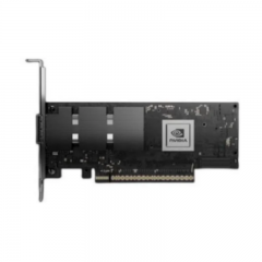
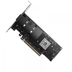
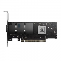
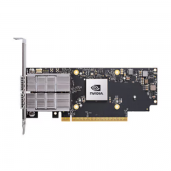
What a 100GBASE-SR4 QSFP28 link requires
100GBASE-SR4 is a short-reach 100 Gigabit Ethernet optical interface intended for multimode-fiber data-center links. It is commonly implemented in the QSFP28 form factor and uses a parallel-fiber optical path. The important selection question is not whether an optic fits a QSFP28 cage; it is whether the exact host port, module, MPO channel, fiber category, polarity method, and software configuration are designed to work together.
This article replaces an outdated inventory announcement with a technical deployment guide. It does not make an availability, price, or product-specific compatibility promise. The guidance below explains the requirements that should be checked for the proposed module and complete channel before a 100GBASE-SR4 purchase or installation is approved.
Confirm the physical interface and fiber path
Cisco’s current 100GBASE QSFP documentation identifies its 100GBASE-SR4-S as an MPO-12 interface used for parallel multimode fiber. It lists up to 70 m on OM3 and 100 m on OM4 for that Cisco part. These values are useful examples of a product data sheet; they are not a universal distance guarantee for every “100G SR4” module or every existing MPO cable plant.
Start with an as-built channel map. Identify the equipment ports, module interface, trunk and patch-cord part numbers, multimode fiber category, fiber count, connector type, cassette or panel locations, polarity method, route length, and number of mated connections. An MPO-12 connector does not, by itself, prove that a channel has the correct fiber mapping or loss budget for SR4.
Measure the installed path rather than using the straight-line distance between racks. Include the length of equipment cords, horizontal and vertical routing, trunks, cross-connects, and service loops. Use the proposed module’s current data sheet to establish the applicable fiber type, reach, channel-loss allowance, power, temperature, and connector requirements. Preserve a margin appropriate to the project rather than designing exactly at a headline maximum.
Parallel optics require a controlled polarity method
SR4 uses multiple optical paths, so end-to-end polarity is a central design requirement. Every trunk, cassette, adapter, and patch cord must preserve the intended transmit-to-receive mapping. A channel can contain compatible modules and good multimode fiber but still remain down if the polarity method or connector gender does not provide the required lane alignment.
Define the polarity method before installation, document it on the channel drawing, and test it as part of acceptance. Do not combine components from different polarity schemes without a verified mapping diagram. Label trunk ends, cassettes, and patch fields so that maintenance staff can identify the circuit and the intended orientation without disconnecting live infrastructure.
If the design uses a breakout, confirm the host switch’s documented breakout support, the required cable or module type, and the operating-system configuration. A 100G port is not automatically capable of every lower-rate breakout merely because a cable is physically available. Host hardware, port group, software release, and approved optics or cabling must all support the selected mode.
Compare SR4 with other 100G media deliberately
100G interfaces are not interchangeable. Cisco’s 100G documentation illustrates options that use MPO parallel multimode fiber, duplex LC multimode links, duplex single-mode links, wavelength-division multiplexing, direct-attach copper, and active optical cables. Each option has a distinct connector, fiber requirement, reach, power profile, and host qualification condition.
Choose SR4 when the actual route, parallel multimode infrastructure, connector system, and host interfaces fit the SR4 architecture. A duplex LC 100G module may be more appropriate when the site has suitable duplex infrastructure and the selected application supports it. For longer or structured connections, a single-mode interface may be preferable. Do not choose a module merely because it says “100G”: the physical layer must match the channel that is already installed or being built.
Fiber upgrades also need careful analysis. OM3, OM4, and OM5 label different multimode-fiber performance categories. The proposed SR4 module data sheet, not a generic fiber label, determines supported reach for that module. Verify the actual installed components, channel loss, and connector quality before reusing a legacy path.
Validate host compatibility, FEC, and power
Review the exact switch, router, NIC, or transport host with its current compatibility matrix. Record the platform model, port, hardware revision, Network Operating System or firmware release, approved module coding, and power limits. A transceiver that works in one platform should not be assumed to be supported by another QSFP28 port.
Set and validate the required port configuration, including speed, FEC, and any link-training or breakout settings specified by the host vendor. FEC behavior can differ among interfaces and platforms. Do not copy a configuration from a different module family without checking the relevant documentation. A link may be recognized physically yet fail to establish or report errors when the two endpoints do not agree on their configuration.
Thermal and power limits also matter in high-density systems. Data sheets identify power and temperature categories for specific modules. Confirm that the selected optic and host port are suitable for the actual rack environment, airflow, and port density. Avoid relying on a commercial-temperature or low-power value taken from an unrelated part number.
Install and accept the channel systematically
- Confirm the two endpoints, port modes, approved module part numbers, and planned 100G application.
- Verify the MPO channel map, fiber category, route length, connector interfaces, polarity method, and loss-budget assumptions.
- Inspect and clean optical interfaces using the procedures appropriate to the installed connector system.
- Install the modules, apply the approved port and FEC settings, and confirm that the host recognizes the expected interface.
- Check operational link state, rate, alarms, available diagnostics, and error counters at both ends.
- Run sustained traffic appropriate to the service, recheck counters and stability, then store the results with the cable record.
Diagnose issues in the right order
When a new SR4 link does not come up, first verify endpoint mapping, module identifiers, fiber type, MPO orientation, polarity, connector cleanliness, seating, and port configuration. Then check platform compatibility, software support, FEC, and the channel budget. This sequence distinguishes common configuration and physical-channel causes from a genuine module fault.
Where diagnostics are available, compare values with the exact module’s published alarm and warning limits. Diagnostics are helpful evidence, but they do not replace polarity verification, compatibility review, or channel testing. Keep the cable schedule, test record, module identities, and port configuration together so that later troubleshooting and replacement are repeatable.
Technical RFQ checklist
A request for 100GBASE-SR4 connectivity should include the endpoint platforms and ports, target application, desired operating rate, multimode-fiber category, MPO interface and polarity method, fiber count, actual route length, connection count, required FEC or port profile, rack environment, compatibility requirement, quantity, labeling, and acceptance test. Ask for the current data sheet for the exact proposed module and confirm its documented assumptions against the channel plan.
The reliable outcome is not an “in-stock 100G optic.” It is an accepted end-to-end link in which the QSFP28 host, SR4 module, MPO channel, polarity, configuration, and test results are all known to agree.
