 dsale@topsfp.com
 English
 русский
 español
 العربية
 中文
中文



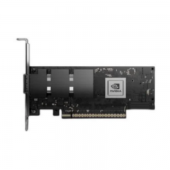
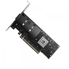
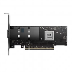
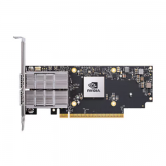
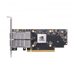
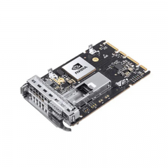
Plan 40G and 100G optics as an end-to-end link
40GbE and 100GbE optical links are used across data-center aggregation, spine, storage, interconnect, and campus environments. The correct interface is not chosen only by headline speed or pluggable form factor. It depends on the host port, electrical lane architecture, target application, fiber type and count, connector system, channel loss, route length, FEC behavior, software support, and the design’s future migration path.
IEEE’s 40 Gb/s and 100 Gb/s Ethernet task force completed its work with IEEE Std 802.3ba-2010, creating a foundation for multiple physical-layer approaches. Since then, module and host options have continued to evolve. A project should therefore use the current documentation for the exact platform and optical module rather than treating an old product announcement or a general market claim as a design specification.
Start with the host port and intended application
Record the exact switch, router, NIC, or transport platform; port type; hardware revision; operating-system or firmware release; and vendor compatibility matrix. A QSFP-shaped port does not inherently establish support for every 40G or 100G optic, cable, or breakout configuration. Hardware and software may support different operating modes, power levels, FEC choices, and qualification lists.
Define the service that the link must provide. Is it a short rack-to-rack connection, a leaf-to-spine uplink, a structured-cabling channel, a campus link, or a data-center interconnect? Identify the required rate, redundancy, latency and availability constraints, real route length, existing fiber plant, connector interfaces, and expected future change. This information determines whether a parallel multimode interface, duplex single-mode interface, passive or active direct-attach cable, or a coherent solution is appropriate.
Do not rely on an assumed port mode. If a 100G port is intended to connect to lower-rate interfaces through an adapter or breakout arrangement, confirm the exact host’s supported map, the compatible module or adapter, the operating-system configuration, and any restrictions. A physical connector may accept a module while the port still lacks the software or lane support needed for the planned service.
Choose media based on the complete channel
High-speed interfaces can use materially different media. A short-reach multimode optic may use parallel fibers and an MPO/MTP connector, whereas a long-reach duplex single-mode optic may use wavelength multiplexing and LC connectors. Direct-attach copper and active optical cables can simplify short equipment links, but their lengths are fixed and their electrical requirements must be validated with the host. These options cannot be exchanged simply because their modules occupy a similar QSFP form factor.
Cisco’s 100G QSFP documentation illustrates the diversity of media options. Its 100G portfolio includes modules for multimode, single-mode, duplex, parallel, and other applications; its descriptions specify different connector types and reaches. Cisco also documents a QSFP28-to-SFP28 adapter use case for selected 100G ports. These are vendor- and platform-specific examples, not a universal promise that every QSFP28 port can operate at 25G, 10G, or 1G through any adapter.
Map the full route before choosing the interface. Include patch cords, trunks, cassettes, adapters, panels, splices, and every mated connection. Use current component data sheets to establish insertion-loss assumptions and applicable channel limits. A link can be below the optical module’s published maximum distance and still fail because it has more connection loss, a different fiber category, poor polarity, or insufficient engineering margin.
Respect lane count, fiber count, and polarity
Interface naming alone does not show the internal lane structure. Different 40G and 100G optical families may use multiple electrical or optical lanes, and their physical interfaces can call for different fiber counts and polarity methods. Before building or reusing a cable plant, document the required transmitter-to-receiver mapping, connector gender, fiber count, cassette type, and breakout architecture.
For duplex links, verify transmit-to-receive polarity across the entire channel. For parallel-fiber links, validate the lane map through trunks, panels, and cassettes. A high-quality cable assembly will not compensate for a mismatched polarity method or an incorrect breakout arrangement. Treat the link’s mapping diagram as a controlled engineering document and update it when a migration changes the interface type.
When migrating from 40G to 100G, do not assume that existing cabling is automatically reusable. Determine whether the chosen 100G application uses the same fiber count, connector type, wavelength plan, and channel loss assumptions as the existing 40G link. If it does not, plan the new trunks, cassettes, or patching explicitly rather than attempting an improvised conversion.
Compatibility, FEC, and management
Host compatibility is a complete system question. Check the module or cable compatibility matrix, port power limits, prescribed FEC mode, speed setting, autonegotiation behavior where applicable, firmware requirements, and diagnostics support. An optical module that is detected by the host may not establish a stable link if its peer or port configuration does not agree.
Forward Error Correction must be selected according to the exact host and interface documentation. It can affect link margin and interoperability, but it is not a universal setting to copy from another port. Record the approved FEC configuration with the cable and module part numbers, and confirm both endpoints use the intended profile before troubleshooting the optical path.
Where digital diagnostics are available, capture a baseline after installation. Parameters such as module temperature, supply voltage, transmit power, receive power, and alarms can assist operations, but only when interpreted against the exact module’s published thresholds. Pair diagnostic data with interface error counters and a documented physical-channel record.
Installation and acceptance procedure
- Confirm the approved host platforms, ports, software versions, interface mode, and module or cable part numbers.
- Verify the route, fiber type and count, connector interfaces, polarity method, and expected channel loss.
- Inspect and clean optical connections; install the components using the manufacturer’s handling and bend-radius limits.
- Apply the approved speed, FEC, and any required breakout or adapter configuration.
- Confirm operational state, rate, diagnostics where available, alarms, and error counters on both ends.
- Run sustained service or traffic testing, then record the final configuration and acceptance result.
Procurement checklist
A technical request for 40G or 100G connectivity should identify the two host platforms, exact ports, intended Ethernet application, media and connector type, fiber category or single-mode specification, fiber count, route length, connection count, FEC and configuration requirement, environment, compatibility constraints, quantity, labeling, and acceptance test. Request the current data sheet for the proposed module or cable and verify that its assumptions match the documented channel.
The result should be a maintainable link design, not an unqualified “40G/100G solution” claim. When host support, media, lane mapping, channel budget, configuration, and tests all agree, the optical layer is prepared for both reliable service and future migration.
